Introduction
When designing industrial flooring, walkways, or platform systems, engineers and plant managers must determine the correct load-bearing capacity for their chosen grating material. FRP grating load tables provide the essential data needed to match grating specifications with application requirements. These tables serve as the definitive reference for understanding how fiberglass reinforced plastic grating performs under various load conditions, spanning distances, and safety margins.
This comprehensive technical reference guide explains everything you need to know about these critical engineering resources — from what they contain and how to read them, to calculating load capacities and applying the data in real-world design scenarios. Whether you are evaluating standard-duty ratings for light pedestrian traffic or heavy-duty data for industrial vehicle access, this guide covers the key principles that ensure safe, code-compliant installations.
By the end of this article, you will be able to confidently interpret any grating manufacturer's load data, perform basic capacity calculations, and select the right grating type for your specific project requirements.
What Are FRP Grating Load Tables?
An FRP grating load table is a structured data chart published by grating manufacturers that specifies the maximum allowable loads a given grating panel can support across various support spans. These tables are the engineering foundation for selecting and specifying fiberglass grating in construction, industrial, and infrastructure projects.
At its core, a load table answers a fundamental question: given a specific grating type, thickness, and support spacing, how much weight can it safely carry? The data accounts for the material properties of fiberglass reinforced plastic — including its anisotropic strength characteristics, resin-to-glass ratio, and manufacturing method (molded vs. pultruded).
These tables are essential because FRP grating behaves differently from steel grating. FRP is lighter, non-corrosive, and non-conductive, but it also has different deflection characteristics and requires careful span-to-load ratio management. Without consulting the correct reference data, engineers risk under-specifying the grating, leading to excessive deflection or structural failure.
Key Components of a Load Table
Every published load table includes several standard data fields that engineers must understand:
- Grating Type and Series: Identifies the specific product line — molded or pultruded, mesh size, and resin system (polyester, vinyl ester, or phenolic).
- Panel Thickness: Typically ranges from 1" (25 mm) to 2" (50 mm), with some heavy-duty variants up to 3" (75 mm).
- Support Span: The distance between bearing supports, usually listed in inches or millimeters. Common spans range from 12" to 48".
- Load Rating: Expressed as uniform distributed load (UDL) in pounds per square foot (psf) or kilopascals (kPa), and concentrated load in pounds (lbs) or kilonewtons (kN).
- Deflection: The maximum vertical displacement at the given load, typically limited to L/100 or L/200 (span divided by 100 or 200).
- Safety Factor: Usually 1.5 to 2.0 for FRP grating, depending on the application standard (ASME, OSHA, or local building codes).
How to Read FRP Grating Load Tables
Knowing how to read FRP grating load tables is a critical skill for engineers, procurement specialists, and installation contractors. While the layout varies slightly between manufacturers, the fundamental structure remains consistent. Here is a step-by-step approach to interpreting any manufacturer's data:
Step 1: Identify the Grating Specifications
Start by locating the header information that identifies the grating type, resin system, and overall dimensions. This confirms which product the published data applies to. For example, a molded grating with 1.5" thickness and 38% open area will have different load characteristics than a pultruded bar grating of the same thickness.
Step 2: Read the Span Column
The leftmost column typically lists support center-to-center spans in ascending order. Common standard spans include 12", 18", 24", 30", 36", and 48". The shorter the span, the higher the permissible load. Always confirm whether the span is measured center-to-center or clear span (the actual open distance between supports).
Step 3: Cross-Reference Load and Deflection
For each span, the table shows the maximum uniform load that produces a deflection of L/100 or L/200. Some data sheets provide two columns — one for allowable load at L/100 and another at L/200. More conservative designs should use the L/200 values.
Step 4: Check Concentrated Loads
Many published charts include a separate section or column for concentrated (point) loads. This is the maximum force that can be applied at a single point, typically at the center of the span, without exceeding allowable deflection or stress limits.
Here is a simplified example for a 1.5" molded FRP grating:
| Span (in) | Span (mm) | UDL at L/100 (psf) | UDL at L/200 (psf) | Concentrated Load (lbs) |
|---|---|---|---|---|
| 12 | 305 | 450 | 225 | 1,500 |
| 18 | 457 | 300 | 150 | 1,000 |
| 24 | 610 | 200 | 100 | 750 |
| 30 | 762 | 140 | 70 | 500 |
| 36 | 914 | 100 | 50 | 350 |
Note: This table is illustrative. Always consult the manufacturer's certified load data for actual project specifications.
Load Ratings in FRP Grating Load Tables
Understanding the specific load ratings published by manufacturers is essential for matching grating performance to application demands. Grating panels are tested according to standardized methods — typically ASTM E2359 or similar international standards — to establish certified ratings.
Uniform Distributed Load (UDL)
Uniform Distributed Load represents the total weight evenly spread across the entire grating surface. This is the most common loading scenario for flooring applications. UDL is expressed in pounds per square foot (psf) or kilopascals (kPa). For typical industrial walkways, UDL ratings range from 100 psf (4.8 kPa) for light pedestrian access up to 600 psf (28.7 kPa) or more for heavy-duty platforms.
When evaluating UDL ratings, consider the FRP grating load tables for industrial flooring specifically. These published resources account for factors such as impact loading from foot traffic, vibration from machinery, and the cumulative weight of equipment and personnel. A well-designed industrial floor system using FRP grating typically requires a minimum UDL capacity of 200 psf (9.6 kPa) at the specified support span.
Concentrated Load
Concentrated load (also called point load) refers to a force applied at a single location on the grating panel. This simulates scenarios such as a forklift wheel, a machinery leg, or a person standing in one spot. In most manufacturer data sheets, concentrated loads are significantly lower than distributed loads because the stress is concentrated in a smaller area.
For safety, engineers should check both the UDL and concentrated load ratings when designing for mixed-use scenarios. For example, a platform that stores evenly distributed pallets (high UDL) but also sees occasional forklift traffic (high concentrated load) must satisfy both conditions.
Special Load Considerations
Beyond basic load ratings, several factors can affect real-world performance of FRP grating:
- Temperature Effects: High temperatures reduce resin strength. Many published tables include temperature derating factors for applications above 100°F (38°C).
- Chemical Exposure: Certain chemicals can degrade the glass-resin bond over time, effectively reducing the rated capacity. Always cross-reference the chemical resistance guide with the load data.
- Dynamic Loading: Applications involving vibration, oscillation, or impact forces may require applying additional safety factors beyond the static table values.
Standard vs Heavy Duty FRP Grating Load Tables
One of the most common questions engineers ask is whether different FRP grating types have different load tables. The answer is yes — and the differences are substantial. The two primary categories are standard-duty and heavy-duty FRP grating, and each has its own distinct published data reflecting different construction methods and material properties.
Standard FRP Grating Load Tables
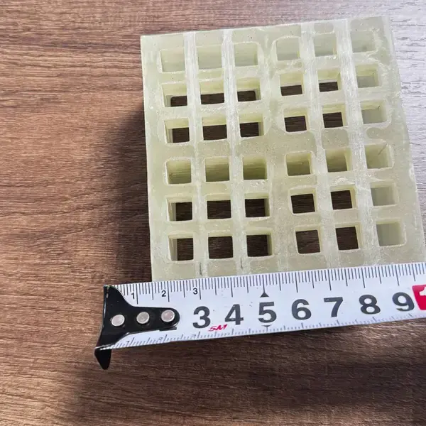
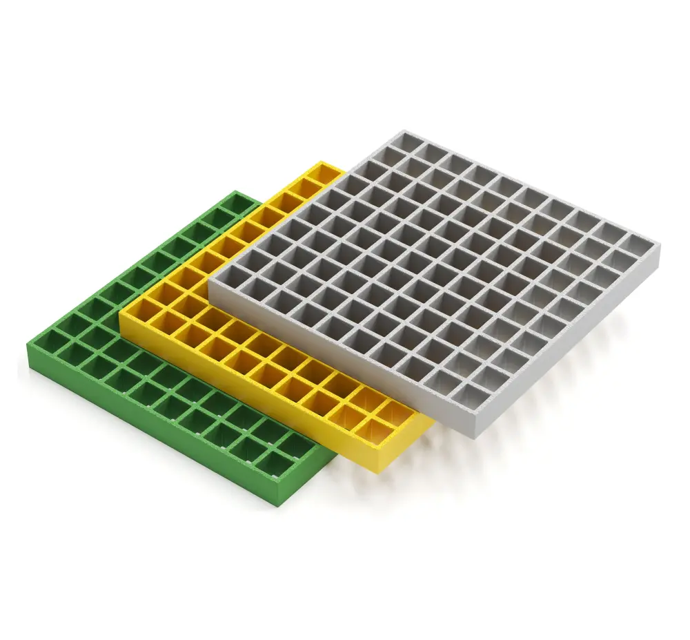
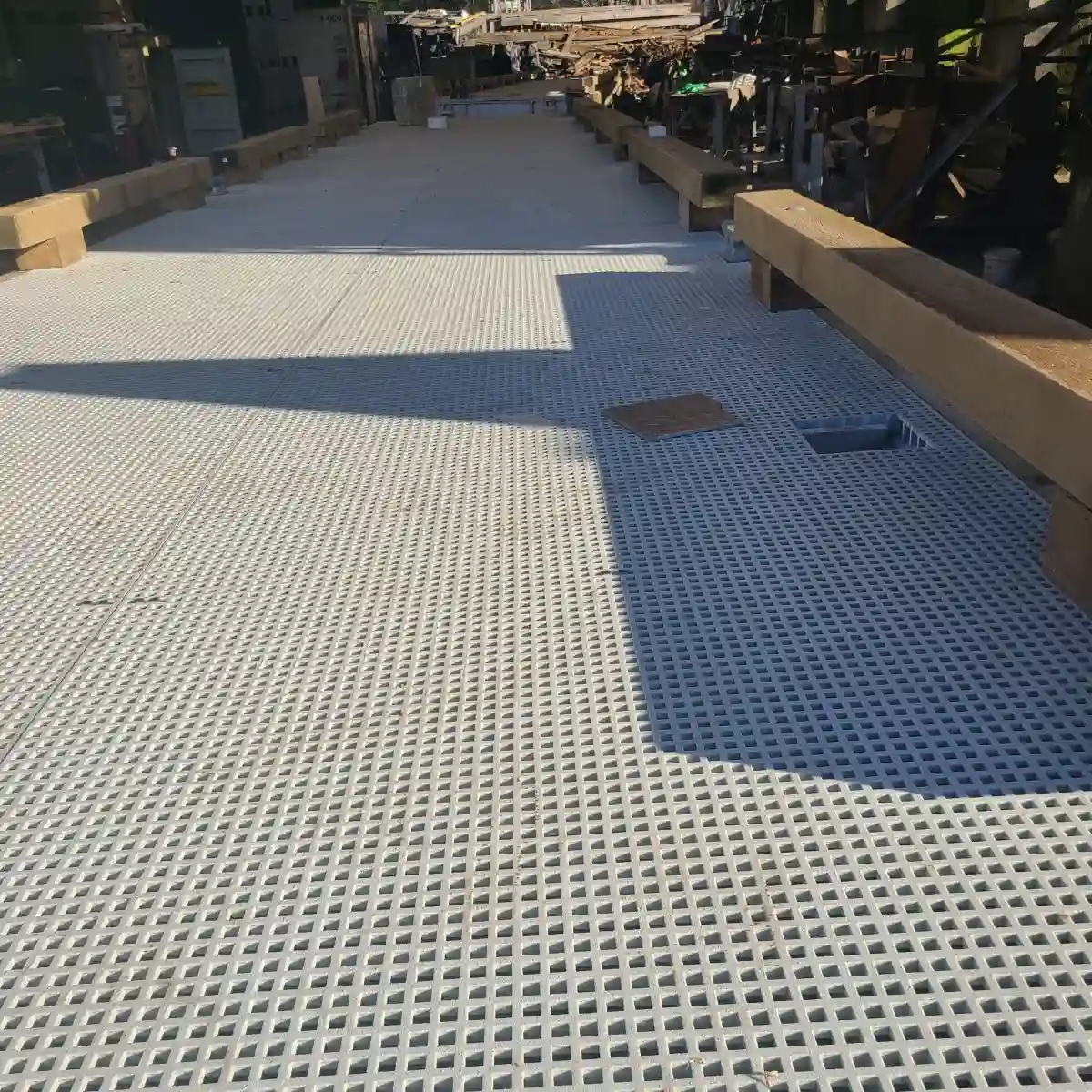
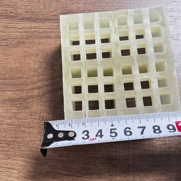
Standard FRP grating load tables typically cover molded grating with thicknesses of 1" (25 mm) and 1.5" (38 mm). This type of grating is manufactured by depositing fiberglass strands and resin into a mold and curing it under heat. Standard molded grating offers a good balance of strength, weight, and cost for applications such as:
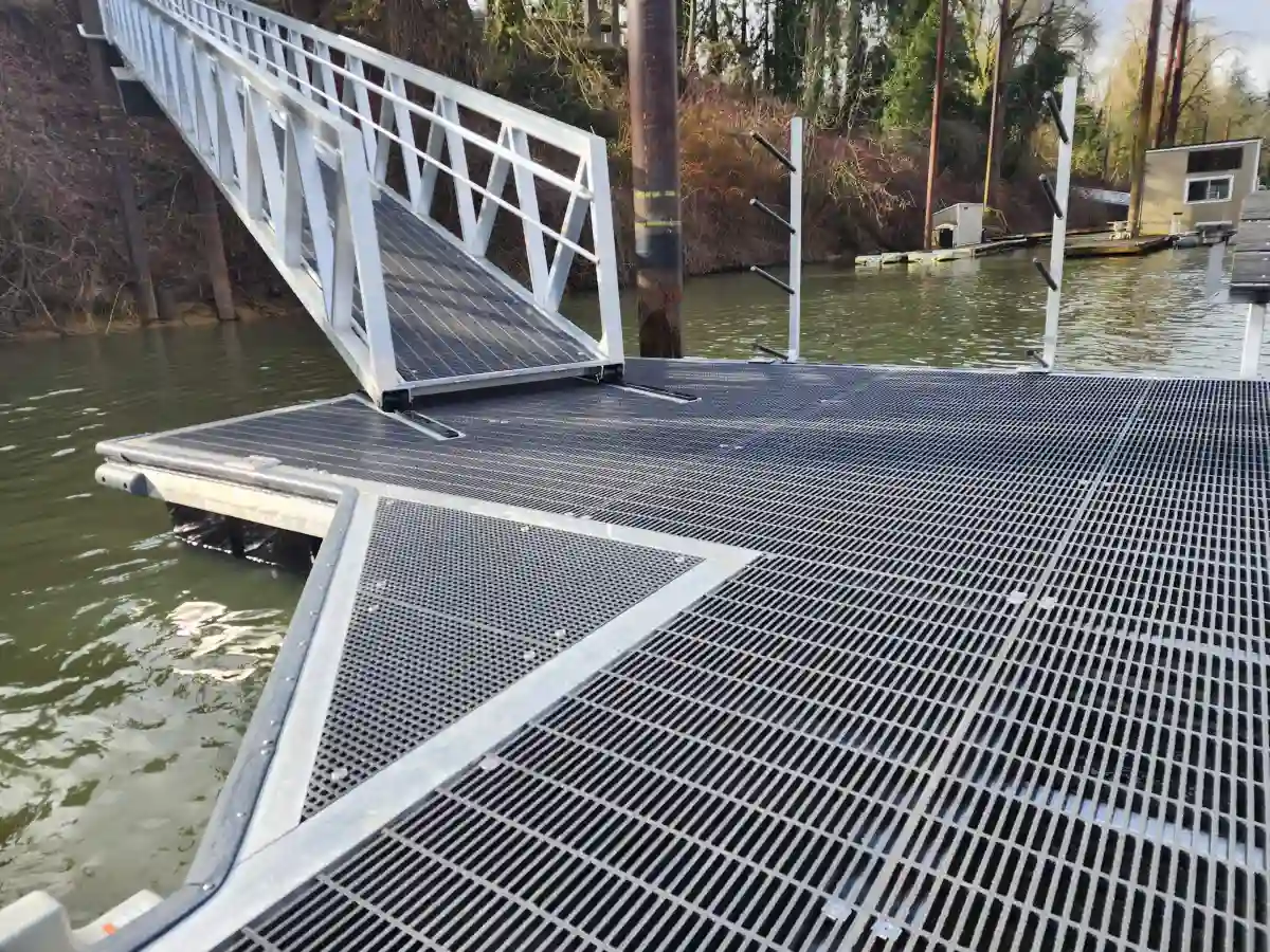
- Pedestrian walkways and catwalks
- Light-duty platform flooring
- Drainage covers and trench grates
- Stair treads and mezzanine flooring
Standard molded grating typically supports uniform loads ranging from 100 to 400 psf depending on span, with deflection limits of L/100 or L/200. These ratings are widely available from manufacturers and are suitable for most commercial and light industrial applications.
Heavy Duty FRP Grating Load Tables
Heavy duty FRP grating load tables cover thicker, more robust grating panels designed for demanding industrial environments. Heavy-duty FRP grating typically uses pultruded construction — a continuous manufacturing process that produces bars with higher glass content and greater longitudinal strength. Common thicknesses include 1.5" (38 mm), 2" (50 mm), and even 3" (75 mm) for extreme applications.
Heavy-duty grating is used in:
- Vehicle access platforms and roadway covers
- Heavy equipment staging areas
- Chemical plant flooring with high load requirements
- Offshore platform decking
- Mining and heavy industrial walkways
The ratings in heavy-duty published data can reach 800 psf or more, with concentrated load capacities exceeding 5,000 lbs. These documents also typically list more conservative deflection limits (L/200 or even L/250) due to the critical nature of the applications.
Key Differences Between Standard and Heavy Duty Data
When comparing standard and heavy-duty data sheets, pay attention to these critical differences:
- Span ranges: Heavy-duty tables often list longer maximum spans (up to 60" or more) since the thicker bars provide greater stiffness.
- Safety factors: Heavy-duty applications frequently require higher safety factors (2.0 vs. 1.5) due to the consequences of failure.
- Deflection criteria: Heavy-duty tables may use stricter deflection limits (L/200 vs. L/100).
- Temperature derating: Heavy-duty tables usually include more detailed temperature correction factors for high-heat environments.
Maximum Span and Load Capacity Calculations
Determining the maximum safe span for a given load is one of the primary reasons engineers consult these reference charts. The maximum safe span is the distance between supports at which the grating can carry its rated load without exceeding allowable stress or deflection limits. An FRP grating load span table organizes this data in a clear, searchable format for quick engineering reference.
Basic Load Calculation Formula
While published tables provide pre-calculated values for standard spans, engineers sometimes need to calculate capacity for non-standard conditions. Understanding the calculation methodology involves applying fundamental beam mechanics to the grating's section properties.
The key variables in any load calculation are:
- w = uniform distributed load (psf or kPa)
- L = support span (in or mm)
- E = modulus of elasticity of the FRP material (typically 1.5–2.5 × 10⁶ psi for molded, 3.0–4.5 × 10⁶ psi for pultruded)
- I = moment of inertia of the grating cross-section
- δ = maximum allowable deflection
For a simply supported beam with uniform load, the maximum deflection is calculated as:
δ = (5 × w × L⁴) / (384 × E × I)
By rearranging this formula, you can determine capacity for spans that fall between the standard values listed. Most manufacturers provide software tools or interpolation guides to simplify this process.
Maximum Span Determination
Every FRP grating load span table directly answers the question: what is the longest support spacing I can use for my required load? To find this:
- Identify your design load — total uniform load including dead load (grating weight) plus live load (people, equipment, materials).
- Select your deflection limit — typically L/100 for pedestrian applications or L/200 for more stringent requirements.
- Consult the manufacturer data — find the row where the rating at your chosen deflection limit meets or exceeds your design load.
- Read the corresponding span — this is your maximum allowable support spacing.
For example, if your design requires 150 psf with L/200 deflection, and the chart shows that a 24" span supports 150 psf at L/200, then 24" is your maximum span. Exceeding this would require a thicker grating panel or additional intermediate supports.
Deflection Limits and Safety Factors
Understanding the safety factor in FRP grating load tables is crucial for safe design. The safety factor accounts for uncertainties in material properties, manufacturing variations, installation conditions, and long-term performance.
Typical safety factors used in FRP grating design include:
- 1.5: Minimum for pedestrian-only applications per ASME standards
- 2.0: Recommended for industrial flooring with occasional vehicle traffic
- 2.5: Required for critical applications such as public access platforms and bridge decking
- 3.0: Used in seismic zones or where impact loading is expected
Deflection limits are equally important. While FRP grating can often handle loads beyond its rated capacity without catastrophic failure, excessive deflection creates an unsafe walking surface and can accelerate wear at support points. Always verify that your chosen grating meets both the strength (stress) and serviceability (deflection) criteria in the data sheet.
How to Use FRP Grating Load Tables for Design
Knowing how to use published load data for design transforms raw numbers into safe, cost-effective grating specifications. Here is a practical design workflow that engineering teams can follow:
Step 1: Define Design Requirements
Before opening a manufacturer's data sheet, document your project's key parameters:
- Total design load (dead + live) in psf or kPa
- Available support spacing based on structural steel layout
- Environmental conditions (temperature range, chemical exposure, UV exposure)
- Applicable building codes and safety standards (OSHA, ASME, IBC)
- Deflection limit requirements (L/100, L/200, or project-specific)
Step 2: Select Candidate Grating Types
Based on your requirements, identify 2-3 grating candidates. For light pedestrian access, start with standard molded grating. For industrial vehicle access, consider pultruded heavy-duty grating. For chemical environments, specify vinyl ester or phenolic resin systems and verify that the published data includes appropriate chemical derating factors.
Step 3: Cross-Reference with Published Data
For each candidate, check the table at your required span. The value must exceed your design load at the specified deflection limit. If none of the candidates work at your span, you have three options:
- Reduce the span by adding intermediate support beams
- Increase grating thickness to a heavier-duty product
- Accept a higher deflection if the application allows (e.g., L/100 instead of L/200)
Step 4: Apply Safety Factors
Manufacturer data sheets typically list ultimate load values. Your design should apply the appropriate safety factor to arrive at the allowable service load. For example, if the chart shows an ultimate load of 400 psf at a given span, and your required safety factor is 2.0, the allowable design load is 200 psf.
Step 5: Verify with Manufacturer
Always verify your selections with the grating manufacturer before finalizing specifications. Manufacturers can provide certified load test data, account for unique installation conditions, and offer guidance on bearing details, fastener spacing, and cutout reinforcements that affect installed capacity.
FRP grating load tables for industrial flooring should always be the primary reference when designing for manufacturing plants, warehouses, processing facilities, and other industrial environments where floor loading is a critical safety consideration.
Where to Find Load Tables for Different Grating Types
Knowing where to obtain manufacturer data for different grating types ensures you always have access to accurate, certified information for your projects.
Manufacturer Technical Data Sheets
The most reliable source for load data is the grating manufacturer's official technical documentation. Reputable manufacturers publish certified tables that have been verified through independent laboratory testing. These documents typically include:
- Complete load-span-deflection data for all product series
- Temperature derating factors
- Chemical resistance compatibility charts
- Installation and bearing details
- Applicable standards and certifications (ASTM, ANSI, CSA)
Online Resources and Digital Tools
Most major FRP grating manufacturers now offer digital versions of their load data, including interactive selection tools. These online resources allow engineers to input design parameters (load, span, deflection limit) and receive instant grating recommendations. Some manufacturers also provide downloadable CAD details and BIM objects that incorporate load data directly into building information models.
Industry Standards Organizations
Several standards organizations provide guidance on FRP grating load ratings and testing protocols:
- ASTM E2359: Standard test method for determining the load capacity of FRP grating
- ASME B30.20: Below-the-hook lifting devices (relevant for lifting applications)
- OSHA 1910.23: Walking-working surfaces (defines minimum load requirements)
- ACI 440: American Concrete Institute guide for FRP reinforcement
Requesting Custom Load Data
For projects with unique requirements — such as non-standard panel sizes, special resin systems, or unusual support configurations — most manufacturers will perform custom calculations and provide a project-specific data sheet. This service is particularly valuable for large-scale industrial projects where the cost of over-engineering would be significant.
When requesting custom data, provide the manufacturer with:
- Exact support spacing and bearing width
- Required design load with safety factor
- Environmental exposure conditions
- Any special cutout or penetration requirements
Conclusion
FRP grating load tables are an indispensable tool for any engineer, architect, or facility manager working with fiberglass reinforced plastic grating. They provide the certified data needed to select the correct grating type, determine safe support spacing, and ensure compliance with building codes and safety standards.
To summarize the key takeaways from this guide:
- These published tables specify maximum allowable loads for given spans, accounting for grating type, thickness, and deflection limits.
- Standard FRP grating load tables cover lighter-duty applications like pedestrian walkways and trench covers, while heavy duty FRP grating load tables address demanding industrial flooring and vehicle access applications.
- Knowing how to read FRP grating load tables involves understanding span columns, UDL vs. concentrated load ratings, and deflection criteria.
- Safety factors of 1.5 to 2.5 are commonly applied, depending on the application's criticality.
- Always verify design selections with the manufacturer's certified data and consider environmental factors such as temperature and chemical exposure.
Whether you are designing a new platform, evaluating an existing installation, or specifying grating for a chemical plant floor, consulting the correct reference data is the first step toward a safe, durable, and cost-effective solution. Bookmark your preferred manufacturer's technical resources, understand the data they provide, and never hesitate to request custom calculations for non-standard applications.
For more detailed information on specific grating products, load calculations, and design assistance, contact our engineering team or visit our technical resources page for downloadable charts and selection guides.