Introduction
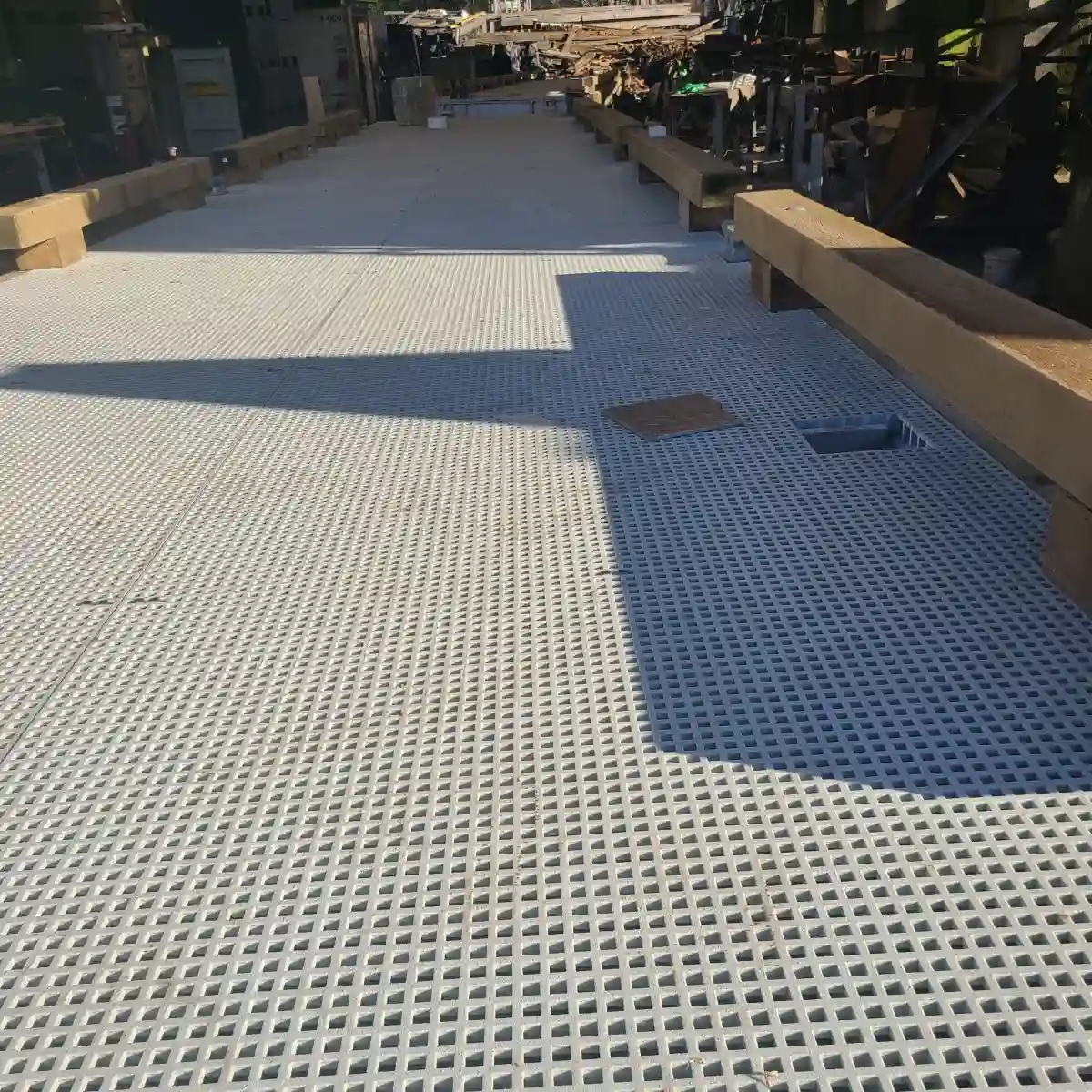
When designing industrial flooring, walkways, or platforms with fiberglass reinforced plastic (FRP) grating, one of the most critical engineering decisions you will face is selecting the correct FRP grating span specification. The span — the distance between supporting beams or joists under a grating panel — directly determines the load capacity, deflection, and safety of the entire structure.
Understanding how to read and apply an FRP grating span specification is essential for engineers, plant managers, and safety officers who need to ensure their grating installations meet both performance requirements and regulatory standards. A miscalculated span can lead to excessive deflection, premature fatigue, or even catastrophic failure under load.
This comprehensive guide covers everything you need to know about FRP grating span specifications: what they are, how to determine the correct span for your application, how span affects load capacity, standard span dimensions, safe calculation methods, and how FRP compares to steel grating. By the end, you will be equipped to make informed decisions for your next FRP grating project.
What Is an FRP Grating Span Specification?
An FRP grating span specification is the engineered guideline that defines the maximum allowable distance between support points for a given FRP grating panel under a specific load condition. In practical terms, the span specification tells you how far apart your support beams or bearing bars can be placed while still ensuring the grating can safely carry the intended load without excessive bending or failure.
The span specification is not a single fixed number — it varies based on several factors including the type of FRP grating (molded vs. pultruded), the resin system used, the panel thickness and bar spacing, and the nature of the applied load (uniform distributed load vs. concentrated point load). Manufacturers publish FRP grating load span tables that show safe span distances for each product configuration at various load ratings.
A typical FRP grating span specification includes:
- Maximum span distance — the longest recommended unsupported length, usually given in inches or millimeters
- Load rating — the maximum safe load in pounds per square foot (psf) or kilonewtons per square meter (kN/m²)
- Deflection limit — the maximum allowable deflection, typically L/100 or L/200 (span divided by 100 or 200)
- Safety factor — usually 1.5 to 3.0 depending on the application and building code requirements
Key Elements of a Span Specification
A complete FRP grating span specification document from a manufacturer will include several key technical elements that engineers must understand before specifying grating for a project. These standard FRP grating dimensions and span data form the basis for safe installation.
| Specification Element | Description | Typical Values |
|---|---|---|
| Panel Depth (Height) | Thickness of the grating panel from top to bottom | 1", 1.5", 2" (25mm, 38mm, 50mm) |
| Bar Spacing (Center-to-Center) | Distance between adjacent load-bearing bars | 1.5", 2", 3" (38mm, 51mm, 76mm) |
| Span Range | Recommended support spacing for the panel | 12" to 48" (305mm to 1219mm) |
| Load Rating | Maximum safe uniform load capacity at given span | 100 to 1,000+ psf |
| Deflection Limit | Maximum allowable panel deflection as fraction of span | L/100, L/150, L/200 |
The panel depth has the greatest influence on span capability. A 2-inch deep pultruded FRP grating can typically span 36-48 inches under moderate loads, while a 1-inch grating is limited to 12-24 inches. Bar spacing also matters — tighter spacing (1.5" center) distributes loads more evenly and allows slightly longer spans than wider spacing (3" center).
How to Determine the Correct Span for FRP Grating
Determining the correct span for your FRP grating installation requires matching your application requirements to the published FRP grating span specification for your chosen product. The process involves identifying the expected loads, selecting an appropriate safety factor, and consulting manufacturer data to find the maximum span that satisfies all constraints.
Step 1: Identify the design loads. These include the dead load (weight of the grating itself plus any permanent fixtures), live load (people, equipment, vehicles, or stored materials), and environmental loads (wind, snow, seismic). For most industrial flooring applications, the live load is the dominant factor.
Step 2: Determine the required safety factor. OSHA and IBC typically require a minimum safety factor of 1.5 for industrial grating, though many engineers specify 2.0 or higher for pedestrian walkways and 3.0 for areas where the grating supports critical equipment.
Step 3: Select a grating type and depth. Pultruded FRP grating offers higher strength-to-weight ratios and longer span capabilities than molded FRP grating of the same depth, making it the preferred choice for large-span applications.
Step 4: Consult the manufacturer FRP grating load span table for your selected product. These tables list the maximum allowable span for each load rating, typically at several deflection limits (L/100, L/150, L/200).
Factors That Influence Span Selection
Several factors influence the correct span selection for an FRP grating installation, and all of them must be considered when interpreting the FRP grating span specification for your project:
- Type of Resin System: Vinyl ester and phenolic resin systems offer higher heat resistance and corrosion resistance than standard polyester, but they do not significantly affect span capacity. The fiberglass reinforcement (E-glass vs. E-CR glass) and glass content (typically 60-70% by weight in the load direction) have a greater impact on structural performance.
- Load Type and Duration: Static uniform loads (e.g., stored equipment) allow longer spans than dynamic concentrated loads (e.g., forklift traffic). Impact loads from dropped objects or moving vehicles require the most conservative span selection.
- Environmental Conditions: Elevated temperatures above 150°F (65°C) reduce the mechanical properties of FRP grating, requiring shorter spans. Similarly, exposure to certain chemicals can degrade the resin over time, which should be accounted for with a larger safety factor.
- Support Conditions: Simply supported spans (grating resting on beams at both ends) are the most common configuration. Continuous spans (grating spanning three or more supports) can carry slightly higher loads due to moment redistribution, but the difference is modest with FRP grating.
- Deflection Criteria: Different applications have different deflection tolerances. For pedestrian walkways, L/100 is often acceptable. For platforms supporting sensitive equipment, L/200 or even L/300 may be required to prevent vibration and misalignment.
How Span Affects FRP Grating Load Capacity
The relationship between span distance and load capacity is one of the most important concepts in FRP grating span specification. As the span increases, the load capacity decreases exponentially — not linearly. This means that doubling the span can reduce the safe load capacity by a factor of four or more, depending on the grating configuration and loading pattern.
This inverse relationship exists because bending moment in a simply supported beam under uniform load is proportional to the square of the span length (M ∝ L²). As the span grows, the internal stresses in the grating bars increase dramatically, requiring thicker bars, tighter spacing, or deeper panels to maintain the same load rating.
For practical engineering purposes, the three key span-related performance parameters are:
- Ultimate load capacity — the load at which the grating would structurally fail. This is determined by the flexural strength of the fiberglass bars and is rarely the governing criterion in well-designed installations because deflection limits are typically reached first.
- Working load capacity — the maximum safe load accounting for the safety factor. This is the value engineers use for design and appears in manufacturer standard FRP grating dimensions tables.
- Deflection under load — how much the grating bends at the center of the span under the working load. This is usually the limiting factor, especially for pedestrian walkways where excessive deflection causes discomfort and a perception of instability.
The Relationship Between Span and Load Capacity
The direct relationship between span and load capacity governs every FRP grating installation. Understanding this relationship is essential for correctly applying an FRP grating span specification to real-world designs.
Uniform Load Capacity vs. Span: For a simply supported FRP grating panel under a uniformly distributed load (UDL), the maximum bending stress is calculated as σ = (w × L²) / (8 × S), where w is the load per unit length, L is the span, and S is the section modulus. Since L is squared in this equation, increasing the span from 24 inches to 36 inches (a 50% increase) nearly doubles the bending stress in the grating bars, requiring the load to be reduced proportionally.
Concentrated Load Capacity vs. Span: Point loads — such as a forklift wheel or a machine foot — create even more severe span-dependent stresses. The bending moment for a point load at midspan is M = (P × L) / 4. While this relationship is linear rather than quadratic, concentrated loads typically produce higher local stresses that can cause individual bearing bars to fail before the overall panel reaches its uniform load limit.
Practical Consequence: This is why heavier-duty applications require either deeper grating panels (which increase section modulus) or shorter spans (which reduce bending moment). An FRP grating load span table captures all these variables in a single reference, allowing engineers to quickly determine the maximum span for a given load or the maximum load for a given span.
Standard FRP Grating Span Specifications
Manufacturers publish standard FRP grating span specifications that provide engineers with reliable span limits for each product series. While exact values vary between manufacturers, the following table represents typical span ranges for commonly used FRP grating configurations under standard industrial loading conditions (100 psf uniform load, L/100 deflection limit).
| Grating Type | Panel Depth | Bar Spacing | Max Span (in) | Max Span (mm) |
|---|---|---|---|---|
| Molded FRP | 1" (25mm) | 1.5" center | 18" | 457 mm |
| Molded FRP | 1.5" (38mm) | 1.5" center | 24" | 610 mm |
| Molded FRP | 2" (50mm) | 1.5" center | 30" | 762 mm |
| Pultruded FRP | 1" (25mm) | 2" center | 24" | 610 mm |
| Pultruded FRP | 1.5" (38mm) | 2" center | 36" | 914 mm |
| Pultruded FRP | 2" (50mm) | 2" center | 48" | 1219 mm |
These values represent the maximum span for standard FRP grating under typical conditions. The maximum span for FRP grating can be extended beyond these figures by using deeper panels, tighter bar spacing, higher glass content, or by accepting a lower load rating. However, spans exceeding 48 inches generally require custom engineering and are rarely cost-effective compared to adding intermediate supports.
It is important to note that these standard spans assume simply supported conditions with proper bearing of at least 1 inch (25mm) on each end support. Grating ends should always be fully supported across the entire width of the panel, never cantilevered beyond the last support unless specifically designed for it.
Standard Span for Heavy Duty FRP Grating
Heavy duty FRP grating applications — such as industrial platforms supporting machinery, vehicle access ways, and mezzanine flooring — require more robust span specifications than standard pedestrian walkways. The standard span for heavy duty FRP grating is typically shorter than standard grating spans because the load requirements are significantly higher.
For heavy duty applications with load ratings of 300 psf or more, the following span guidelines apply:
- Deep pultruded grating (2" to 3" depth): Maximum span of 24-36 inches for loads of 500-1,000 psf. These deep sections feature thicker bearing bars (typically 3/16" to 1/4") and are often reinforced with additional cross-rods for lateral stability.
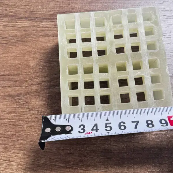
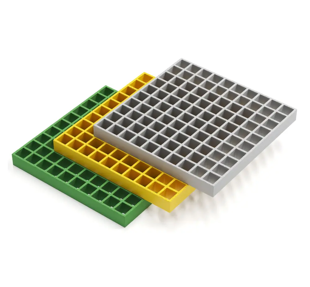
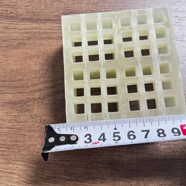
- Heavy duty molded grating (1.5" to 2" depth): Maximum span of 18-24 inches for loads of 300-500 psf. Molded grating for heavy loads uses higher-density glass content and may incorporate square mesh patterns instead of rectangular for improved bidirectional strength.
- I-Beam or T-Bar pultruded profiles: These specialized profiles can span up to 48 inches under heavy loads by using an I-beam cross-section that maximizes the section modulus for a given weight. They are commonly used in chemical plant platforms and offshore oil rig flooring.
When selecting a heavy duty FRP grating, always consult the manufacturer certified load tables rather than relying on generic span data. The FRP grating load span table for heavy duty products will reflect the actual tested performance of the specific product, including safety factors mandated by applicable building codes.
How to Calculate Safe Span for FRP Grating Panels
Calculating the safe span for FRP grating panels involves applying fundamental beam mechanics to the specific grating configuration. While manufacturer FRP grating load span tables are the most reliable source for span data, engineers should understand the underlying calculations to verify manufacturer claims and to evaluate non-standard applications.
Basic Formula for Safe Span Under Uniform Load:
The maximum allowable span (L_max) for a given uniform load (w) can be calculated from the flexural strength of the grating:
- L_max = √(8 × σ_allowable × S / w)
Where σ_allowable is the allowable bending stress (ultimate strength divided by safety factor), S is the section modulus per unit width of the grating panel, and w is the uniform load per unit length. For concentrated loads, the formula adjusts to L_max = (4 × σ_allowable × S) / P for a mid-span point load P.
Deflection Check: In most FRP grating installations, deflection — not ultimate strength — is the limiting factor. The maximum deflection under uniform load is calculated as:
- δ_max = (5 × w × L⁴) / (384 × E × I)
Where E is the modulus of elasticity of the FRP composite in the span direction (typically 2.5-4.0 × 10⁶ psi for pultruded grating) and I is the moment of inertia. The calculated deflection must not exceed the specified limit (e.g., L/100 = 0.36 inches for a 36-inch span).
Span Calculation for Walkways and Platforms
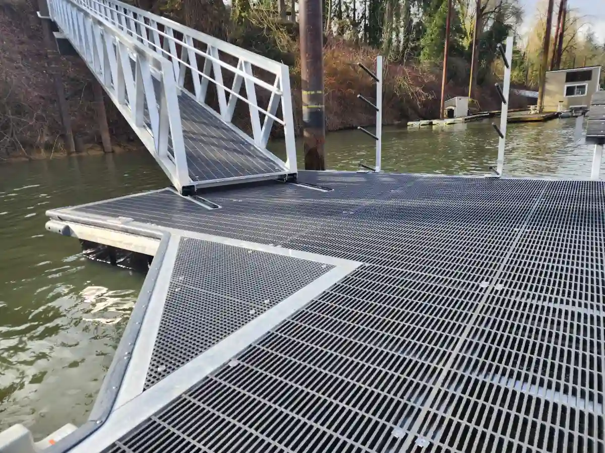
Walkways and pedestrian platforms are the most common application for FRP grating, and calculating the correct span for these applications requires careful consideration of both safety and comfort. When determining FRP grating span requirements for walkways, the deflection criterion is often more restrictive than the strength criterion because excessive bounce or sag can alarm pedestrians even when the structure is technically safe.
Standard Walkway Span Guidelines:
- Light pedestrian traffic (maintenance access, catwalks with occasional use): 1.5" deep pultruded grating at 36" span is adequate for loads up to 100 psf. This configuration is the most common in the FRP grating industry and offers the best balance of cost and performance.
- Moderate pedestrian traffic (frequent walkway use, light equipment access): 2" deep pultruded grating at 36-42" span handles loads up to 150 psf with deflection under L/150.
- Heavy pedestrian traffic (public walkways, elevated platforms with crowds): 2" deep grating at 30" span or less, designed for 200 psf with deflection limited to L/200. These stricter criteria ensure that the walkway feels solid underfoot even when fully occupied.
When calculating FRP grating span for walkways, always use the heaviest reasonably anticipated load condition, not just the average occupancy load. A crowded maintenance walkway during a plant shutdown can easily see loads of 100 psf or more from personnel carrying tools and equipment.
Using FRP Grating Load Span Tables
Manufacturer FRP grating load span tables are the primary engineering reference for selecting the right grating configuration for any application. These tables consolidate the results of physical testing and engineering analysis into a format that allows quick and accurate design decisions. Understanding how to read and apply these tables is essential for anyone working with FRP grating span specification data.
How to Read an FRP Grating Load Span Table:
A typical load span table is organized with panel depth and bar spacing as row headings, and load ratings as column headings. The cell values represent the maximum allowable span in inches for that combination of load and grating configuration. The table typically includes separate sections for different deflection limits (L/100, L/150, L/200).
| Load (psf) | 1" Molded @ 18" | 1.5" Molded @ 24" | 1.5" Pultruded @ 36" | 2" Pultruded @ 48" |
|---|---|---|---|---|
| 75 | 24 | 30 | 42 | 54 |
| 100 | 21 | 27 | 38 | 49 |
| 150 | 17 | 22 | 31 | 40 |
| 250 | 13 | 17 | 24 | 31 |
| 500 | 9 | 12 | 17 | 22 |
Important Table Interpretation Notes:
- All values assume simply supported conditions with proper end bearing
- Values are based on a deflection limit of L/100 unless otherwise noted
- Pultruded grating spans shown are for 2" center-to-center bar spacing; tighter spacing allows longer spans
- Always apply the specified safety factor from the applicable building code when using these values
The standard FRP grating dimensions listed in these tables — depth, bar spacing, and panel width — directly determine which row of the table applies to your selected product. Always verify that the product you are purchasing matches the dimensions used in the load span table you are referencing.
FRP Grating Span vs Steel Grating Span
One of the most common questions engineers ask when switching from traditional materials to composites is how FRP grating span specifications compare with steel grating. The FRP grating span vs steel grating span comparison reveals important differences that affect design decisions, installation costs, and long-term performance.
Key Differences in Span Capability:
- Steel grating typically offers longer maximum spans for the same depth because steel has a much higher modulus of elasticity (29 × 10⁶ psi vs. 2.5-4.0 × 10⁶ psi for FRP). A 2" deep steel grating can easily span 48-60 inches under heavy loads, while FRP grating of the same depth is typically limited to 36-48 inches.
- FRP grating compensates for its lower stiffness with superior corrosion resistance, lighter weight (1/4 the density of steel), and lower installation costs. An FRP installation may require more support beams than a steel installation, but the total installed cost is often lower because no painting, coating, or corrosion protection is needed.
- Weight advantage: FRP grating weighs approximately 4-8 lbs per square foot compared to 10-20 lbs per square foot for steel grating of similar load capacity. This weight reduction reduces the load on the supporting structure, which can offset the need for additional supports.
When to Choose Each Material: Choose steel grating when spans exceed 48 inches, when loads exceed 500 psf, or when the installation environment is dry and non-corrosive. Choose FRP grating when corrosion resistance is required, when weight reduction is critical, when electrical or thermal insulation is needed, or when the total lifecycle cost (including maintenance) favors composites despite the shorter span capability.
FRP Grating Span Specifications for Industrial Flooring
Industrial flooring applications — including mezzanine floors, equipment platforms, trench covers, and heavy-access walkways — impose demanding requirements on FRP grating span specification. These environments typically involve heavy equipment, chemical exposure, and stringent safety regulations that require conservative engineering margins.
Typical Industrial Flooring Span Requirements:
- Chemical processing plants: Span specifications for chemical plant flooring typically range from 24-36 inches using 1.5" to 2" deep pultruded grating with vinyl ester resin. The load requirements are usually 100-200 psf for general access, but may increase to 500+ psf in areas with heavy equipment or drum storage. The FRP grating span specification for chemical environments must also account for potential resin degradation from chemical exposure, which can reduce mechanical properties over time.
- Water and wastewater treatment: Treatment plant walkways and platform flooring typically use 1.5" molded FRP grating at 24-30 inch spans. The primary concern here is corrosion resistance in humid, chemically aggressive environments rather than extreme load capacity. Standard load ratings of 100-150 psf are typical.
- Food processing facilities: These applications require 1.5" to 2" pultruded FRP grating with fire-retardant resin systems. Span specifications are similar to chemical plants (24-36 inches), but with additional requirements for easy cleaning and resistance to frequent washdown with hot water and sanitizing chemicals.
- Offshore and marine platforms: The most demanding industrial flooring applications require 2" to 3" deep pultruded FRP grating with spans of 24-30 inches. These installations must withstand heavy wave action, salt spray, and significant point loads from equipment and personnel. Safety factors of 3:1 or higher are standard.
For any industrial flooring application, the span specification you need must be reviewed and approved by a structural engineer familiar with FRP composite design. Unlike steel, FRP does not yield before failure — it behaves in a linearly elastic manner until sudden rupture — making proper safety margins essential.
Choosing the Right Span for Industrial Flooring Applications
Choosing the right FRP grating span specification for industrial flooring involves balancing multiple competing factors: load requirements, deflection limits, cost constraints, and environmental conditions. Here is a practical step-by-step approach to making the right selection:
1. Define the Design Load: Start with the maximum anticipated load. For industrial flooring, this is typically the greater of: uniform live load (e.g., 100 psf for general access, 250 psf for storage areas), concentrated point load (e.g., 2,000 lb forklift wheel load), or impact load (e.g., dropped tools or materials). Use the highest value for your span calculation.
2. Set the Deflection Limit: For industrial flooring supporting equipment, use L/200 or tighter. For general walkways, L/100 is usually acceptable. For platforms with sensitive instrumentation, L/300 may be required to prevent vibration-induced errors.
3. Select the Grating Depth: Deeper grating allows longer spans but adds cost and weight. Use the manufacturer FRP grating load span table to find the shallowest (least expensive) panel that meets your span and load requirements at the chosen deflection limit.
4. Account for Environmental Factors: If the installation is in a corrosive environment, increase the safety factor by 25-50% to account for long-term material degradation. For elevated temperatures above 150°F, consult the manufacturer for derating factors that reduce allowable stress at higher temperatures.
5. Verify Support Conditions: Ensure the support structure can accommodate the selected span with proper bearing. All FRP grating panels require a minimum of 1 inch of bearing on each end, and the support beams must be level and properly aligned to prevent uneven loading.
What Happens If FRP Grating Span Exceeds Specification?
Exceeding the manufacturer-recommended FRP grating span specification can have serious consequences for safety, performance, and service life. Understanding these risks is essential for anyone responsible for designing, installing, or inspecting FRP grating systems.
Immediate Consequences of Over-Spanning:
- Excessive deflection: The most immediate and visible effect of exceeding the specified span is excessive deflection at the center of the panel. The grating will sag noticeably under load, creating a tripping hazard and an unsettling "bouncy" feel for pedestrians. Even if the grating does not fail immediately, deflection beyond L/100 is considered unacceptable for most applications.
- Reduced safety factor: The safety factor built into the span specification is eroded or eliminated entirely when the span is exceeded. A grating installed at 48 inches when the specification calls for 36 inches may have a safety factor of only 1.0 or less — meaning it is operating right at the point of failure under the rated load.
- Accelerated fatigue: FRP materials, while corrosion-resistant, are susceptible to fatigue under cyclic loading. Excessive spans increase the stress range that the grating experiences with each load cycle, leading to micro-cracking in the resin matrix and eventual failure of individual bearing bars. This is particularly dangerous because fatigue damage is often invisible until catastrophic failure occurs.
Long-Term Risks:
- Creep deformation: FRP composites can deform permanently under sustained loads (creep). The creep rate accelerates at higher stress levels, meaning an over-spanned grating panel will sag progressively over time even under constant load, eventually exceeding acceptable deflection limits permanently.
- Connection failure: Overspanning increases the reaction forces at the support points. The fasteners and clips holding the grating in place may fail under these higher loads, causing the panel to shift or lift off its supports. This is especially dangerous on elevated walkways where a panel could be dislodged entirely.
- Vibration problems: Longer spans have lower natural frequencies, making the grating more susceptible to resonant vibration from foot traffic or machinery. This can cause discomfort for pedestrians, noise problems, and accelerated wear at connection points.
If a grating installation must span farther than the manufacturer specification allows, the solution is not to exceed the specification but to upgrade to a deeper or higher-strength grating product. Alternatively, adding intermediate support beams to reduce the effective span is often the most cost-effective solution.
Conclusion
Understanding FRP grating span specification is fundamental to designing safe, durable, and cost-effective industrial flooring and walkway systems. The span specification determines not only how far apart your support beams can be placed, but also the load capacity, deflection behavior, and long-term performance of the entire installation.
Key takeaways from this guide:
- An FRP grating span specification defines the maximum allowable distance between supports for a specific grating product under a specific load. It is not a universal number but varies with grating type, depth, bar spacing, resin system, and application conditions.
- Span and load capacity are inversely related — longer spans mean dramatically lower load capacities. Always verify both the strength and deflection criteria when selecting a span.
- Manufacturer FRP grating load span tables are the best source of span data. Use them in combination with the appropriate safety factors and building code requirements for your specific application.
- For industrial flooring, typical spans range from 18-36 inches for molded grating and 24-48 inches for pultruded grating, depending on load requirements and deflection limits.
- Comparing FRP grating span vs steel grating span, steel generally allows longer spans for equivalent depth, but FRP offers significant advantages in corrosion resistance, weight reduction, and total lifecycle cost.
- Standard FRP grating dimensions — including panel depth and bar spacing — directly affect span capability. Deeper panels and tighter spacing allow longer spans and higher load ratings.
- Never exceed the manufacturer span specification. The consequences — excessive deflection, reduced safety factor, fatigue, creep, and potential failure — can compromise safety and lead to costly repairs or replacements.
By applying the principles and span calculation methods covered in this guide, engineers and specifiers can confidently select the right FRP grating configuration for any industrial walking or working surface.